How reliable is TVT (10th Value Thickness) in radiation shielding calculations?
Published: Feb 20, 2023
Source: Ionactive Consulting Radiation Protection Resource
Prelim
There is quite a lot of information in this article! Some of the terms used like linear attenuation coefficient are described elsewhere in our glossary, but we will summarise all terms in this resource to keep everything together. The aim of this article is to explore how reliable TVT (or HVT) are for simple radiation shielding problems (and their solutions) involving gamma emitters from radioactive materials. We will address similar issues for x-rays from x-ray generators in separate resource later.
For a neat summary of TVT and HVT please consider reading the following Ionactive resource before returning here. Glossary summary of 'TVT' , 'How do I convert TVT to HVT (or the other way around)?' and 'How do I convert TVT (10 value thickness) values to attenuation for Gamma or X-ray sources of radiation?'.
In order to ensure this resources focus remains practical, we will consider a very simple radiation shielding problem and examine the solution by considering TVT (or HVT) alone, and then by a more in-depth consideration to determine how reliable they are.
The shielding problem (and desired solution)
We have a certain Cs-137 radioactive sealed source - so small in physical dimensions that it can be treated as a point source. The dose rate at 1m from this source is 1000 μSv/h (1000 micro Sv/h) - as measured in air by an ion chamber radiation survey instrument.
Progressively we want to reduce this exposure to 1 μSv/h using lead shielding. We will first do this using the TVT for lead (with Cs-137), and then examine the solution by looking more in-depth using attenuation equations, attenuation coefficients and buildup factors.
Cs-137 has been chosen because the gamma emissions from its decay product (Cs-137 → Ba-137m → Ba-137) is a single gamma ray photon of 662 keV.
Enjoy the ride!
The shielding "problem" using well known TVT data
We will first consider this shielding problem using well known TVT data for radioactive Cs-137 and lead. The TVT is 22mm lead (a reference to this can be found on our own site - TVT for Cs-137 with lead).
We know that a TVT will reduce the dose rate (or dose) to 1/10th of the pre-shielded value. So we have the following:
- 1TVT (22mm lead) will reduce the radiation exposure at 1m to 100 μSv/h.
- 2TVT (44mm lead) will reduce the radiation exposure at 1m to 10 μSv/h.
- 3TVT (66mm lead) will reduce the radiation exposure at 1m to 1 μSv/h.
For this article we are not going to discuss how and where the shielding is placed (i.e. shielding design), but generally you would place the shielding as close to the source as possible.
So far so good. We will now break this down and see how this works from first principles.
Some definitions to start with
The expression we are going to work with is as follows.
I=Ioe-µt
In the above expression we have the following:
Io - gamma dose rate with no shielding
I - gamma dose rate through a radiation shield of thickness t
t - the thickness of the shield (normally expressed in cm)
e - this is raising the following expression to base e
µ - linear attenuation coefficient (normally expressed in units of cm-1)
You may note it is common to work with grams (g) and a length of (cm) in these expressions.
Linear attenuation coefficient (µl)
The linear attenuation coefficient (µ), with units cm-1, is the fraction of gamma ray photons attenuated per unit thickness of the shield. The value of this coefficient is given in tables and data books (references given later), and is specific for a material (e.g. lead) and energy (e.g. 662 keV). Often there is no exact data for the energy desired, so interpolation between two known energies might be required, to find the desired value of µ for a particular case.
Sometimes you may see µ expressed as µl to signify that this is a linear attenuation coefficient. The importance of this will now become clear.
Mass attenuation coefficient (µm)
Other data which might be more readily available is to look up the mass attenuation coefficient (µm). This has the units of cm2/g . The mass attenuation coefficient will be specified for a certain energy (e.g. 662 keV) and the material (e.g. lead). It should be noted that you can obtain the µl coefficient by multiplying the µm coefficient by the density (p) of the shielding material being considered. This is shown as follows.
µl (cm-1) = µm (cm2/g) x p (g/cm3)
That completes the definitions for the moment - a couple more to come later.
A word on geometry
The expression in the previous section assumes perfect geometry (narrow beam geometry with collimation) - something that is not found in real life (i.e. outside a laboratory). Generally the above expression will underestimate the shielding required, but in certain circumstances can also over estimate shielding. Let is consider the two possibilities here.
Underestimation

Photon attenuation dose under estimated
As you will see in the above example, all the photons are in narrow beam geometry and all undergo attenuation before arriving at the detector. You might be able to show this is true in a laboratory, but this is not real life!
Now consider the opposite case (not as likely, but still important).
Overestimation

Photon attenuation dose over estimated
In the above diagram you will note that the source of radiation is NOT collimated (unlike the previous example), but all gamma ray photons still arrive at the detector. This is not realistic!
Now we have considered this, we can return to the following expression, and add some values.
I=Ioe-µt
You may wish to refer back to the original problem. For this first stage we want to reduce the dose rate from Cs-137 at 1m from 1000 µSv/h down to 100 µSv/h (and eventually down to 1 µSv/h). The values to consider are as follows.
Io - 1000 µSv/h
I - gamma dose rate of 100 µSv/h for shield of thickness t (in cm)
t - the thickness of the shield (normally expressed in cm)
e - this is raising the following expression to base e
µ - linear attenuation coefficient (normally expressed in units of cm-1) - 1.27 cm-1.
So how did we get the value of µ (either as µl or µm)? This can be the tricky part as there are loads of reference out there on the web, data books and similar.
The following picture shows an extract from a data table from 'Handbook of Health Physics and Radiological Health', (Table 5.1, section 5-23, third edition) with a derivation of µl from µm.
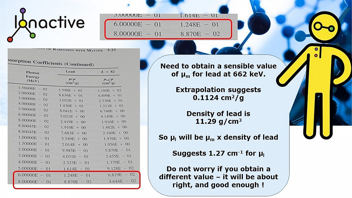
Derivation of µl from µm from data tables
The above derivation shows that the value of µl is likely to be about 1.27 cm-1. We can now evaluate the above expression, noting that we want to find the value of t (in cm). So we have
I=Ioe-µt
100 = 1000 x e-1.27t
0.1 = e-1.27t
-2.3025 = -1.27t
t = 1.81cm (18.1mm)
This result suggests that the lead required is 18.1mm, whereas the TVT to produce a 10 fold reduction (i.e. 1000 µSv/h down to 100 µSv/h) for Cs-137 is reported as 22mm lead. Here is our first indication that the practical values may not match the theory (we know that 22mm lead for a TVT with lead and Cs-137 works practically from experience).
What we now need to consider is the concept of Buildup (B). Before moving on to this, consider a more realistic rendition of gamma ray photon attenuation (from experiment).
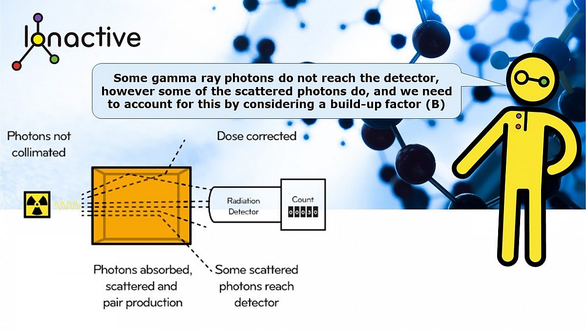
More realistic gamma ray photon absorption in shielding
It is important to provide the following advice - where possible use experimentally derived attenuation factors (sometimes called transmission factors). This might include the use of TVT (or HVT) if the reliability of the data is known. However, as you will see in a moment, the use of TVT may overestimate the shielding required. Take a look at the following experimentally derived data - this is from 'Handbook of Radiological Protection' (UK, 1971).
Note that the lines are not quite straight, but are pretty close to straight for Cs-137. What this tells us is that for Cs-137 and lead, the use of the TVT is pretty reliable even from the first TVT layer (TVT1)
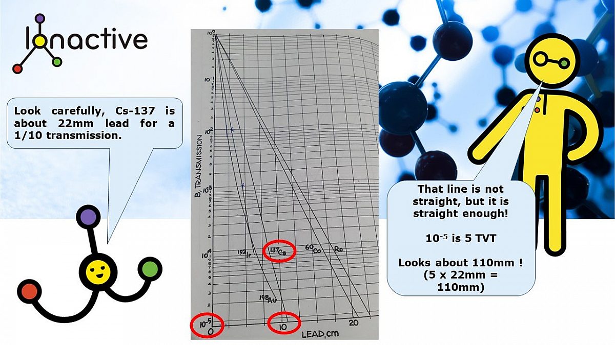
Transmission of gamma rays through lead (broad beam conditions).
Now consider the attenuation of much lower energy x-ray photons in lead. Note how the first few TVT (1/10 reductions in transmission) are different to those later transmissions (the slope changes). This will show that shielding is not so easy for lower energy photons, you will overestimate the shielding required. Now back to buildup.
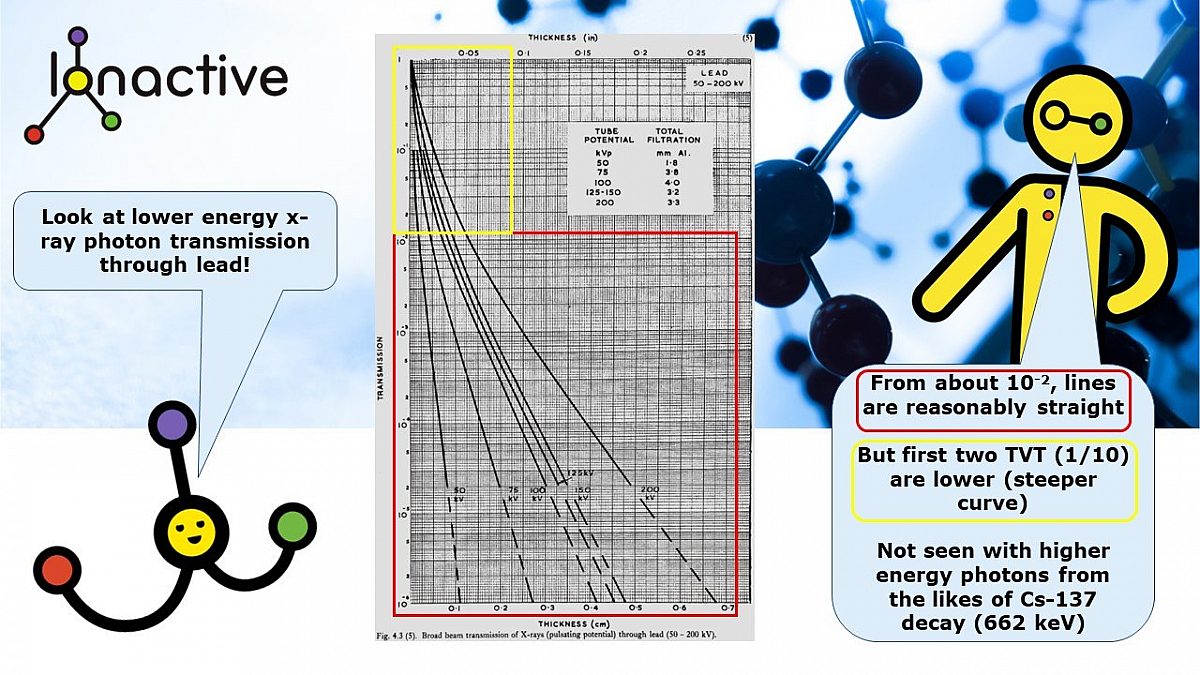
Transmission of lower energy photons (x-rays) through lead.
Buildup
Noting the diagrams given earlier. And the expression:
I=Ioe-µt
We note that this works for good geometry (narrow beam conditions with collimation).
However, real life (in most cases unless in an experimental setup) is poor geometry and broad beam conditions. This will be true always for thicker shields (i.e. several TVT). Hence the above expression assumes that every photon interacts with the shielding material and will be removed (so will not arrive at the detector or contribute to the dose rate at that point). This will underestimate the required shielding because in reality (with broad beams):
- photons will be scattered by the shield but will still arrive at the detector (contributing to dose rate), rather than be lost outside the scenario under consideration.
- some photons that were scattered by the shielding 'outside' the scenario, may be scattered back in towards the detector (contributing to dose rate), following secondary scattering.
As noted earlier, where experimentally available TVT data is proved reliable, then use it!
The buildup factor (B) can be stated as 'the ratio of the intensity of the radiation, accounting for the primary and scattered radiation, at any point in the radiation beam, to the intensity of the primary radiation beam only at that point'.
The buildup factor (B) is influenced by the thickness of the shield, and this causes a problem. In the above expression there are two unknowns.
- The thickness of the shielding required (t)
- The buildup (B) required which is partly determined from the thickness of the shielding (t)
To solve this issue we need to do a guesstimate. If we were using a computer this would be solved by 1000's of iterations to find the ultimate value. However, thankfully this is not required, following a simple tried and tested methodology we can work this out using paper, pen and a calculator.
Some additional terms required when considering buildup
Buildup, from experimental data or computer models, requires that the MFP (mean free paths) are known. This is also known as the relaxation length. This can be calculated from the linear attenuation coefficient (µl) multiplied by the thickness of the shield (t) for the given attenuation required (hence the two unknowns).
MFP = µl x t
We use the following convention to start with. Note earlier that we had calculated , under narrow beam conditions, that 18.1mm of lead was required to reduce the dose rate from Cs-137, at 1m from the source, from 1000 µSv/h to 100 µSv/h.
What we do is to assume narrow beam conditions and then increase the thickness by 1 HVT (half value thickness) to bring the scenario into 'probable' broad beam conditions. 1 HVT in this example is given by the following expression .
HVT = 0.693 / µl
From earlier we note that µl was 1.27 cm-1. Therefore HVT in this example will be 0.546 cm (or 5.46 mm).
So the estimated shielding thickness (for the 1/10 reduction) is 23.56 mm lead, pretty near the assumed TVT of 22mm. This is obtained from the 18.1mm lead considered in the narrow beam earlier consideration, plus the HVT calculated just now. Important - for the purposes of this section, we are assuming no knowledge of the TVT for Cs-137 (22mm lead), otherwise we would have just gone with 22mm - we are not going to cheat this explanation.
From this the relaxation length (mean free path - MFP) can be expressed as :
1.27 x 2.356 = 2.99 (3) relaxation lengths (or MFP). Note we need to ensure we were working in cm.
With this information we are now ready to look up buildup (B) in a table.
Buildup data
The following picture shows an extract from a data table from 'Handbook of Health Physics and Radiological Health', (Table 6.5.1, section 6-19, third edition). The data shows exposure buildup factors for lead, for various MFP (left hand column) and we have highlighted the MFP and energy range we are interested in.
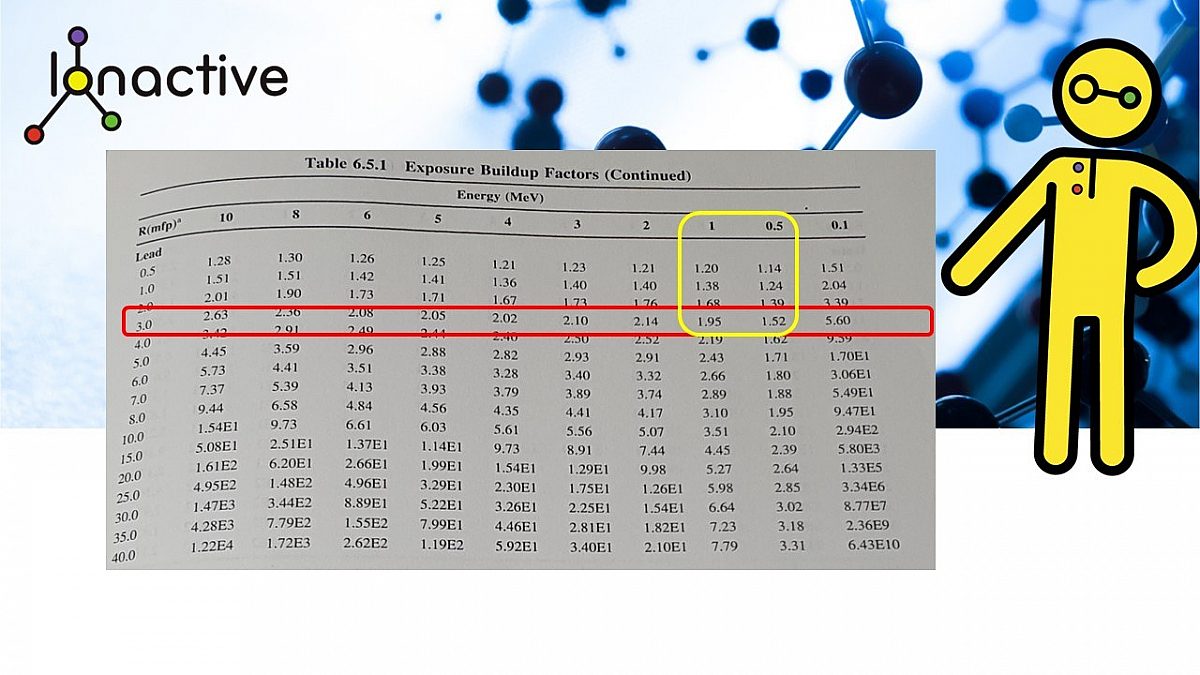
Buildup factors for a MFP of 3 with the energy range of 0.5 MeV to 1 MeV
The interpolation of this data is quite difficult and a little trial and error is required. We require the following:
- Buildup factor for a MFP of 3 for an energy of 662 keV (0.662 MeV).
Since we do not have the curves between the data set we have to assume it is linear. If you do this you will see that the buildup factor (B) under these conditions is about 1.66.
We can then return to this expression and plug the values in .
I=Io x B xe-µt
Note - all we have added is the (B) term
Io - 1000 µSv/h
I - gamma dose rate we want for shield of thickness t (in cm)
t - the thickness of the shield (normally expressed in cm) - 23.56mm (2.356cm)
e - this is raising the following expression to base e
µ - linear attenuation coefficient (normally expressed in units of cm-1) - 1.27 cm-1.
B - buildup factor of 1.66
Note that this time we are evaluating I and not thickness (t).
Solving for I in µSv/h we have 83 µSv/h. This is LESS than required (which might be OK), but this shows that our estimated thickness of 23.56mm is too much, since we were looking for I to be 100 µSv/h. If this were a really unknown situation we would carry on and try adjusting the value of t until we obtained the desired attenuation. However, we know better - we think that 22mm of lead for this problem is a pretty safe bet. So let's try 22mm of lead.
Evaluating the above expression by setting t= 22mm lead (2.2 cm) lead
We now set t=22mm lead (2.2cm lead).
This means that our MFP will change to -
1.27 x 2.2 = 2.8 relaxation lengths (or MFP).
If you look back at the buildup data previously given, then this is so close to 3 MPF that the previous value of 1.66 could be used. However, we did some interpolation and came up with a slightly lower buildup (B) value of 1.6.
This data can now be placed into the expression :
I=Io x B x e-µt
This will look like the following :
I=1000x 1.6 x e-1.27 x 2.2
I is 98 µSv/h, which is near enough 100 µSv/h, especially given the interpolation required.
This is a good result!
Final thoughts (for now)
We started out by being fairly confident that a TVT of 22mm for lead with Cs-137 is pretty reliable (and this value is reported in many publications).
We have shown that the 22mm is reliable and can be determined from first principles considering linear attenuation coefficients, MFP and buildup.
We have shown that the first TVT for lead with Cs-137 (TVT1) is reliable, and so will be further TVTs. This is also supported by the transmission curves given earlier in this article.
This analysis shows that the reported 22mm TVT for lead with Cs-137 will account for realistic broad beam (imperfect) conditions when evaluating radiation shielding.
The analysis has also shown why we picked Cs-137 - it is easy! Other radionuclides with prominent gamma ray photons, with specific probability of emission, each with their own MFP and buildup, would take much longer to evaluate, and using a spreadsheet or computer program would be preferable.
More resource like this will be posted soon. It will be interesting to repeat this analysis with a much lower energy gamma emitter and then consider shielding.
