Radioactive source holders - Dose rate through an aperture
Published: Apr 23, 2024
Source: Dr Chris Robbins, Grallator / Ionactive radiation protection resource
Radioactive source holder on a nuclear gauge
Nuclear gauges come in a number of configurations, sizes and uses etc. Whilst some gauges have moved over to x-ray generator technology, the majority use radioactive sources - typically Cs-137, Ba-133, Am-241, Sr-90 and Kr-85 in the MBq to GBq range. Most configurations are based on placing a radioactive source in one position and allowing it's emissions (gamma rays or beta in the case of Sr-90) to pass through a sample space before arriving at a radiation detector. The attenuation of the radiation within the sample space will be detected and this can be used to provide information about the material in the sample space. The sample space could contain a static sample for analysis, but often contains material that can flow in some way - so many nuclear gauges can be used for process control (the detector providing information for a feedback loop). Other names for these gauges are often nuclear density gauges, radiometric gauges and similar. Nuclear density gauges, as the name suggests, measure density. Noting that density = mass/volume, and that volume (of the sample area) can be engineered and fixed, thickness or level (depth) can also be measured. Some typical uses are as follows:
- Level gauges in a tank of liquid
- Thickness gauge in paper making
- Density gauge in cement manufacturing
- Multi phase flow meters (MPFM) - oil and gas industry
- Fill level in bottles and cans (beverage industry)
The placement of the source within the nuclear gauges will vary on the specific design. Often the source (s) is located within the gauge such that there is no obvious source holder (the gauge is one piece). However some gauges, such as the MPFM mentioned above consist of a venturi pipe where the source is mounted in a shielded source holder one side of the bore, and the detector assembly on the other side of the bore. In this configuration the source holder is treated as a separate part of the gauge and is usually flange bolted to the side of the bore.
Often the nuclear gauge will contain some type of moving source shield such that the source exposure can be controlled (this is useful if the gauge is mounted onside the side of a large tank where person access is required from time to time). Other times it is the source that moves from a safe shielded location and out into the sample area (e.g. this is typical in many nuclear density / moisture gauges used in the construction industry).
For other gauges, such as the MPFM noted above, there is no shutter and the source (via thin collimator / aperture) continuously emits radiation into the venturi bore (radiation protection here is often based on there being no physical access to the bore - e.g. by hand or an arm).
By now you might suspect we will be analysing something to do with a MPFM, or more precisely its source holder - you would be right (!), although the analysis in this article can be applied to many other situations using radioactive sources in shielded container.
What could possibly go wrong?!
A basic mock up of a MPFM configuration is shown in the picture below.
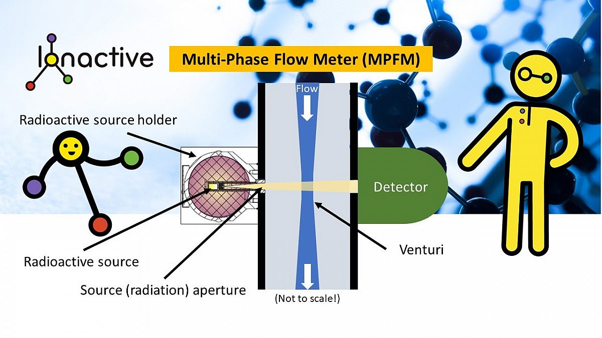
The reason for this resource was born out of a regulator enquiry with one of our clients who install MPFM onto subsea components, for onward shipment to oil fields. The question was along the lines of - '...what would happen if the source holder becomes detached from the MPFM during a reasonably foreseeable event such as dropping the gauge during a lifting procedure ...'. This article will not consider how reasonably foreseeable this event could be. It is assumed the following will occur:
- The source holder is broken off from the MPFM furthest from the flange end.
- The break is clean such that the aperture is located directly at the surface extent of the source holder.
- The event results in the source holder being located on an elevation, roughly truck of body height.
What will the dose rates be some distance from the aperture and how much of the trunk of the body will be exposed at a particular distance?
The analysis which follows will use a Cs-137 source of 35 MBq - the dimensions and shielding properties of the holder are such that at the perimeter surface dose rate is < 5 micro Sv/h at any point, apart from the aperture. This could be scaled for typical MPFM activities (e.g. 11.1 GBq Cs-137) - in this case the overall dimensions of the source holder shielding will scale to meet the < 5 micro Sv/h specified.
Update (May 2024). The information below is now also available as a widget - Dose rate through a small aperture widget.
Over to Dr Chris Robbins to analyse this situation.
Dose rate through an aperture
Dr Chris Robbins, Grallator
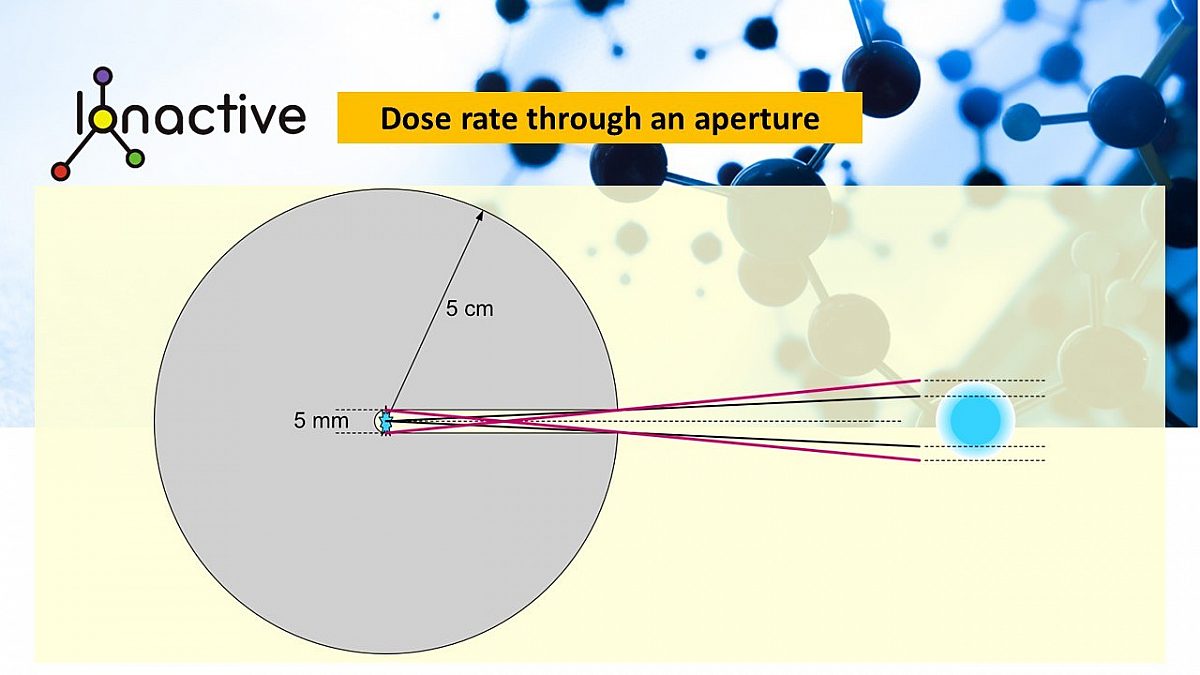
A source is sealed at the centre a solid spherical shield of radius \(r = 5 \space cm\). The shield material is such that the shield absorbs all energy of activity from the source. A hole of diameter \( a = 5 \space mm\) is drilled from the surface to the source as shown below.

Making the assumption that the source is small compared with the hole and so can be approximated as a point source, and assuming the energy released can only be through the aperture (i.e. paths that pass through a thin section of shield near the aperture are ignored), radiative energy will only be detected in a thin cone of subtended angle \(2 \theta\).
Calculating the power density
The energy released per second will radiate outwards and, in the absence of a shield be spread over the surface of a sphere. The power per unit area at a distance \(R\) from the source is given by the inverse square law: \[ P_a = \frac{P}{4 \pi R^2} \] where \(P_a\) is the power per unit area and \(P\) is the total power of the source. This assumes no absorption and energy is spread over the full solid angle of \(4\pi\) steradians. However, as shown in the diagram, only a small fraction of the solid angle is available for energy to escape. The solid angle available is that of a cone subtending the plane angle of \(2 \theta\), which is given by \[ \Omega=4 \pi \space \mathrm{sin}^2 \left( \frac{\theta}{2} \right) \] The fraction of the total energy radiated through the hole, \(f\) is given by the ratio \(\Omega:\Omega_{sp} \) where \(\Omega_{sp} =4\pi \), the solid angle of a sphere,i.e. \[ f=\frac{4 \pi \space \mathrm{sin}^2 \left( \frac{\theta}{2} \right)} {4\pi} = \mathrm{sin}^2 \left( \frac{\theta}{2} \right) \] The total power escaping the shield is then \(fP\). The power density a distance \(R\) along the dotted line above is still given by \(P_a = \frac{P}{4 \pi R^2}\) however, the area over which this applies is limited to that bounded by the rays depicted, i.e. and area \(A=\Omega R^2\).
Putting in numbers
The diagram gives \(r=5 \space cm\) and \( a = 5 \space mm = 0.5 \space cm\). The angle \(\theta\) is related to \(r\) and \(a\) by \[ \mathrm{sin} \left( \theta \right)=\frac{\frac{a}{2}}{r}=\frac{0.25}{5}=0.05 \] This is a small angle, and using the small angle approximation \( \mathrm{sin} \left( \theta \right) \approx \theta \), when \(\theta\) is in radians \[ \mathrm{sin} \left( 0.05 \right) \approx \theta \approx 0.05 \] Similarly, using the small angle approximation gives \[ f= \mathrm{sin}^2 \left( \frac{\theta}{2} \right) = \mathrm{sin}^2 \left( \frac{0.05}{2} \right) \approx {0.025}^2 = 6.25 \times 10^{-4} \] The above states that only about \(\frac{1}{1600}\) of the total radiative energy escapes the shielding sphere.
The solid angle \(\Omega\) is evaluated as \[ \Omega=4 \pi \space \mathrm{sin}^2 \left( \frac{\theta}{2} \right)=4\pi f \approx 4\pi \times 6.25 \times 10^{-4} = \frac{\pi}{400} \space \mathrm{steradians} \] so that the area irradiated at a distance R is given by \[ A=\Omega R^2=\frac{\pi R^2}{400} \] and recall the power density at the same distance is \[ P_a = \frac{P}{4 \pi R^2} \] Notice that the total power over the irradiated area, \(P_I\) is given by \[ P_I = P_aA = \frac{P}{4 \pi R^2} \times \frac{\pi R^2}{400} = \frac{P}{1600} \] i.e. a constant value that is the total power escaping the shield as discovered above.
Plotting the values of \(A\), \(P_a\) and \(P_I\) for \(R\) ranging from 5 cm to 200 cm and \(P=1\) gives the following.
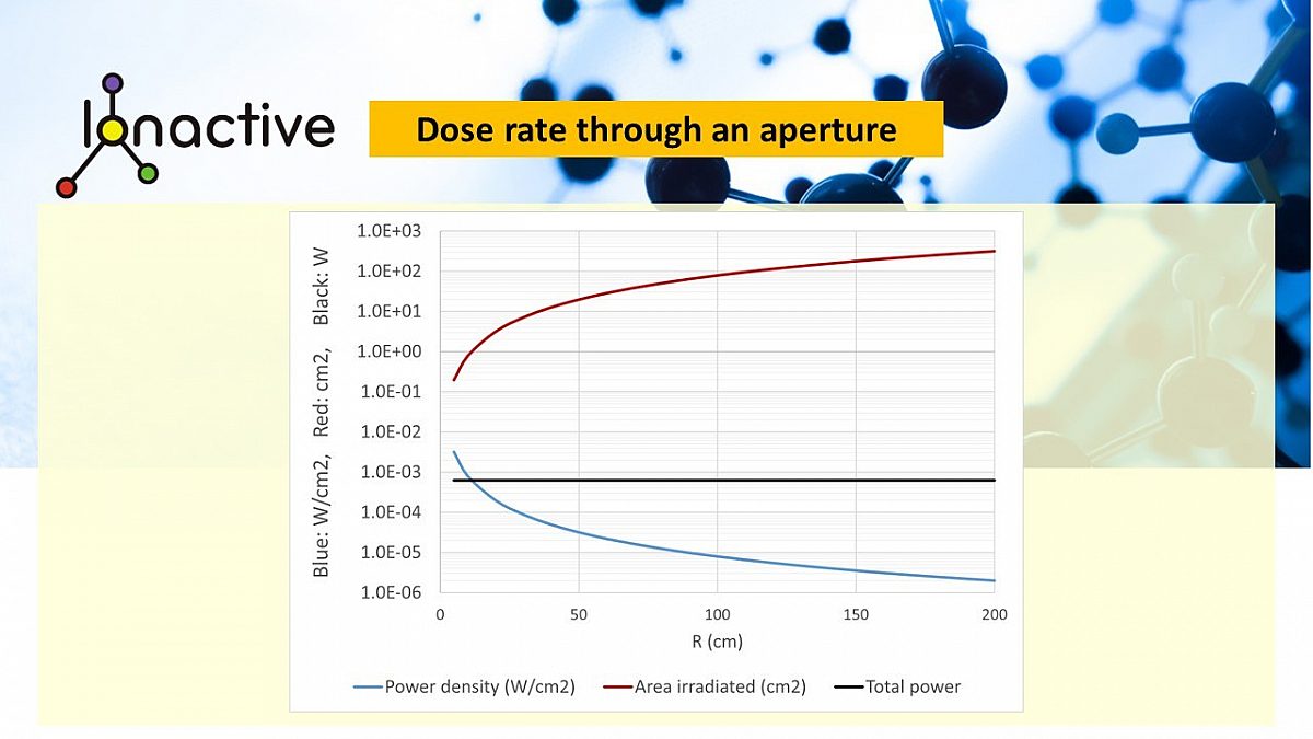
Tabulating several values (note, only shown to three decimal places/significant figures - rounding may occur if replicated by hand):
| \(R \,\, (cm)\) | \(A \,\,(cm^2) \) | \(P_a \,\, (W/cm^2)\) | \( P_I \,\, (W) \) |
| 5 | \(0.196 \) | \(3.18 \times 10^{-3}\) | \(6.25 \times 10^{-4}\) |
| 10 | \(0.785 \) | \(7.96 \times 10^{-4}\) | \(6.25 \times 10^{-4}\) |
| 50 | \(19.635 \) | \(3.18 \times 10^{-5}\) | \(6.25 \times 10^{-4}\) |
| 100 | \(78.540 \) | \(7.96 \times 10^{-6}\) | \(6.25 \times 10^{-4}\) |
| 150 | \(176.715 \) | \(3.54 \times 10^{-6}\) | \(6.25 \times 10^{-4}\) |
| 200 | \(314.159 \) | \(1.99 \times 10^{-6}\) | \(6.25 \times 10^{-4}\) |
Taking the irradiated are above, it is possible to construct the diameter of the area that will be irradiated, \(\Phi\) as a funcion of distance, given below.
| \(R \,\, (cm)\) | \(A \,\,(cm^2) \) | diameter \(\Phi \,\, (cm)\) |
| 5 | \(0.196 \) | \(0.50 \) |
| 10 | \(0.785 \) | \(1.00 \) |
| 50 | \(19.635 \) | \(5.00 \) |
| 100 | \(78.540 \) | \(10.00 \) |
| 150 | \(176.715 \) | \(15.00 \) |
| 200 | \(314.159 \) | \(20.00 \) |
At a distance of 200 cm = 2 m, a circle of diameter 20 cm centred on the dotted line in the diagram will be irradiated. Outside of this are there will be no irradiation. Such an area would, for example, cover a human chest but would not extend to the head, arms or legs.
Putting in more numbers
Assume now that the source is \(^{137}Cs\) with an activity of 35 MBq. To simplify matters we'll ignore the \( \beta \) decay component and only look at the 661.7 keV \(\gamma\) and calculate dose rate.
Total \(\gamma\) power from decay is \( P =\mathrm{Activity} \times \mathrm{Energy\,per\,decay} \), i.e., \[P= 35 \times 10^6 \times 661.7 \times 10^3 \times 1.602 \times 10^{-19}= 3.710 \times 10^{-6} \,\,\,\, W \,\, \mathrm{or} \,\, Js^{-1}\]
The power density at a distance \(R\) cm along the dotted line is given by \[ P_a = \frac{P}{4 \pi R^2} = \frac{3.710 \times 10^{-6}}{4 \pi R^2} \,\,Js^{-1}cm^2 \] The dose rate is given (approximately) by \(P_a \times \left(\mu_{en}/\rho \right) \), where in these units \(\left(\mu_{en}/\rho \right) \) is in \( cm^2g^{-1} \). For air, \(\left(\mu_{en}/\rho \right) = 2.929 \times 10^{-2}\,\,cm^2g^{-1} \). This gives an expression for the absorbed energy rate as \[ D_{Js^{-1}g^{-1}} = \frac{3.710 \times 10^{-6}}{4 \pi R^2} \times 2.929 \times 10^{-2} = \frac{1.087 \times 10^{-7}}{4 \pi R^2} \,\,Js^{-1}g^{-1} \] Using the definition of \(1\,Gy = 1\,Jkg^{-1}\) which requires scaling up from per gramme to per kilogram (multiply by 1000), and converting the absorption time from seconds to hours (multiply by 3600) gives \[ D_{Gyhr^{-1}} = \frac{1.087 \times 10^{-7}}{4 \pi R^2} \times 1000 \times 3600 = \frac{0.391}{4 \pi R^2} \,\,Gyhr^{-1} \] Note, \(R\) is still in cm. At a distance of \(R=5\,\, cm\), i.e. at the aperture mouth the dose rate is \[ D_{Gyhr^{-1}} = \frac{0.391}{4 \pi \times 5^2} = 1.245 \times 10^{-3}\,\,Gyhr^{-1} \] For \(\gamma \) the absorption quality factor is 1, so \(1\,Gy \equiv 1\,Sv\), giving \[ D_{Gyhr^{-1}} = 1.244 \times 10^{-3}\,\,Gyhr^{-1} = 1.245\,\,mSvhr^{-1} \]
The above dose rate only applies at the centre dotted line of the aperture. As the distance increases along this line the dose rate falls in accordance with the inverse square law, but this only applies to a small area centred on the dotted line. This table above is modified to show dose rate and the applicable area as shown below.
| \(R \,\, (cm)\) | \(A \,\,(cm^2) \) | diameter \(\Phi \,\, (cm)\) | D \(\mu Svhr^{-1}\) |
| 5 | \(0.196 \) | \(0.50 \) | \(1244.6 \) |
| 10 | \(0.785 \) | \(1.00 \) | \(311.1 \) |
| 50 | \(19.635 \) | \(5.00 \) | \(12.4 \) |
| 100 | \(78.540 \) | \(10.00 \) | \(3.1 \) |
| 150 | \(176.715 \) | \(15.00 \) | \(1.4 \) |
| 200 | \(314.159 \) | \(20.00 \) | \(0.8 \) |
Is this right?
The expressions above make the assumption that radiation can only emerge from the opening in the shielding. While this is true for, for example, visible light and an opaque shielding material, the situation would not quite be the same for, for example, \(^{137}Cs\) which is a \(\beta^{\,-} / \gamma \) emitter. In this case the \( \beta \) and \(\gamma\) rays would be attenuated by different amounts depending on the radiation type and how much sheilding material they passed through prior to exit. The net result is that instead of a hard circle of irradiation, there would be a wider area affected, with the power density falling outside of the centre area.This is analogous to the umbra and penumbra of a solar eclipse (except we're measuring 'brightness' rather than 'darkness').
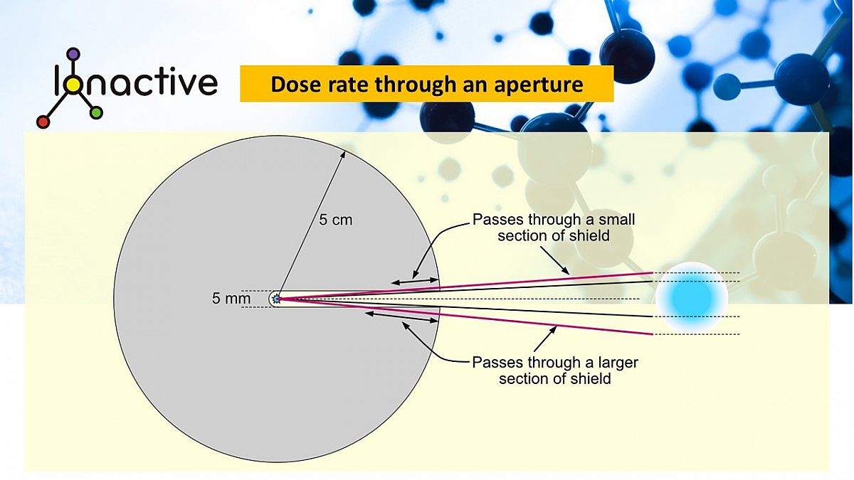
It is reasonably simple to calculate the absorption fraction to apply as a function of the angle of the beam from the centre-line using simple geometry.

A \(\gamma\) photon travels a distance \(r\) to escape the shield. For an angle of travel relative to the hole centre-line, \(\alpha\), and \(\alpha\) being large enough that the path intersects the shielding, the path will be of length \(q\) in air, and length \(p\) in the shielding material. The relationship between \(\alpha \) and \(q\) is given by \[ \mathrm{sin} \left( \alpha \right) = \frac{a/2}{q} \Rightarrow q=\frac{a/2}{\mathrm{sin} \left( \alpha \right)} \] It is obivous that \(p+q=r\) so that \[ p=r-q = r-\frac{a/2}{\mathrm{sin} \left( \alpha \right)} \] From this, the attenuation factor due to linear absorption, \(a_f\) is given \[ a_f=\mathrm{exp} \left( -\lambda p \right) \] for an attenuation coefficient \(\lambda\). For the example of \(^{137}Cs\) and a lead shield, \(\lambda \approx 1 \,\, cm^{-1}\). Using the shield and hole dimensions above allow the following plot and brightness diagram to be constructed. The different path lengths through the shielding material results an a 'fuzzy' edge to the area of irradiation.
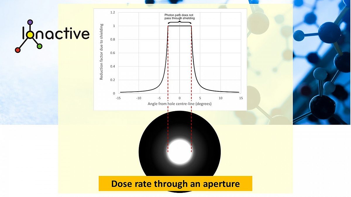
By changing to a logarithmic scale and extending the angle from -90 to +90 degrees from the hole centre line it is easy to see that the tenth value shielding thickness occurs at about \(5^ \circ \) (actually about \(5.3^ \circ \)) and two tenth value thicknesses occur at about \(40^ \circ \) (actually about \(38.7^ \circ \)). The half value thickness occurs at about \(3.3^ \circ \), which is just larger than the angle of \(2.87^ \circ \) at which first contact between the photon path and the shielding occurs.

To put these angles into context, consider an average 1.8 m person standing with their torso on the centre line of the aperture. The dose rate will be a function of the inverse square law distance and the attenuation of any shielding material the photon path passes through, as shown below

The analysis also assumes a point source; in reality, the source may be extended. Under the assumption that only 'line-of-sight' radiation can escape, this will given another mechanism to produce an umbra/penumbra analogous effect due to the various escape paths.Such a geometry will increase the area irradiated, as shown below
In actuality there will be effects from radiation attenuation near the apperture, and the extended nature of the source (and other considerations such as build-up). Mathematical descriptions could be constructed for these effects, or numerical simulation using Monte Carlo techniques could be used. But that's for another note...
Practical considerations from this analysis
The most significant practical result this analysis confirms is that a true whole body dose rate (and therefore whole body dose accumulation) only occurs some considerable distance from the aperture. This is important since the headline dose rate measured close to the aperture could be numerically significant, but exposure potential much less so. Let's use a new (soon to be released) dose rate through an aperture widget, created for Ionactive by Dr Chris Robbins (screen shot is provided now, widget to be release shortly). In this we set the following values.
- Activity - 12 GBq (of Cs-137) - typical for a MPFM.
- Fix the shielded dose rate at no greater than 5 micro Sv/h (requiring a lead shielded of 20 cm diameter).
- Assume the aperture diameter is 6 mm.
- Assume critical person exposed is 2 m away from the aperture.
This situation will look something like the following.
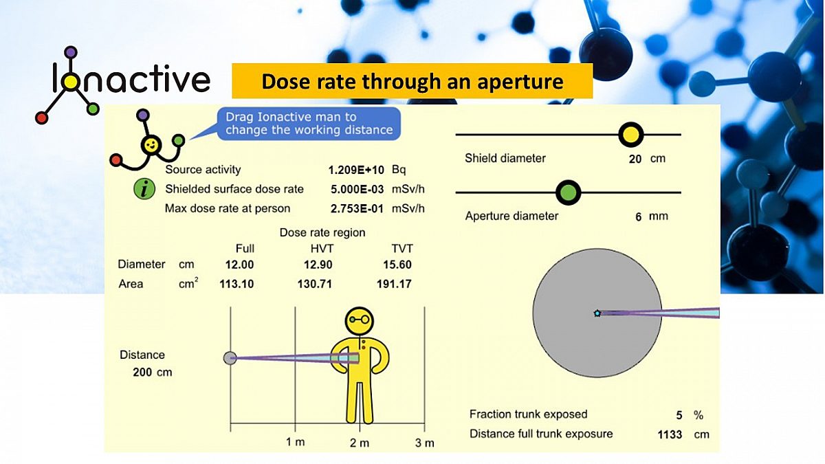
Using our dose rate through an aperture widget to evaluate realistic MPFM activity and dose rate
What we can see is the following important results.
- Headline dose rate at 2m from the source is 275 micro Sv/h.
- For this dose rate, only 5% of the trunk is exposed (so absolutely not a whole body exposure).
- A whole body exposure only becomes relevant at 1133 cm (> 11m) from the source.
- At >11m from the source, dose rate (whole body) is now of the order of 9 micro Sv/h.
This analysis shows that headline dose rate measured (or calculated) close to an aperture in the scenario presented (i.e. radiation accident) is a poor indication of potential whole body dose. It also demonstrates that careful evaluation of whole body dosimetry (if worn) needs to be undertaken to ensure that whole body doses are not exaggerated.
The analysis also reveals likely extremity dose rate (and accumulated exposure) to the hands / eyes (etc) should they be very close to the source aperture.
